
My ClockSquared project has a long history – it goes all the way back to 2015, when it was simply called the “Birthday word clock”. I haven’t spent much time on the project in recent years, but I’ve upgraded the internals a while ago and finally felt like writing a post about it.
Two things in particular bothered me about the design that is shown in my previous post about ClockSquared:
- The so-called “light grid” was made of MDF. Compared to a material such as polyethylene foam (“PE foam”, or “hardfoam”), MDF is relatively expensive, more difficult to process in a laser cutter, much less flexible and much heavier.
- The electronics were quite cumbersome in general. The LED array was made of 11 strips of 11 WS2812B LEDs, which I had to solder together manually, and then all glue into place separately. The microcontroller, an Arduino Uno, was “flapping around in the breeze” within the enclosure, as Dave from the EEVBlog would describe it. The same goes for the buck converter and the real-time clock module. Not very good.
In this new design I’ve addressed both issues. The MDF light grid has been replaced by a polyethylene foam light grid and all the electronics (except control buttons and power port) have been integrated into a single large PCB.
Improvement: light grid
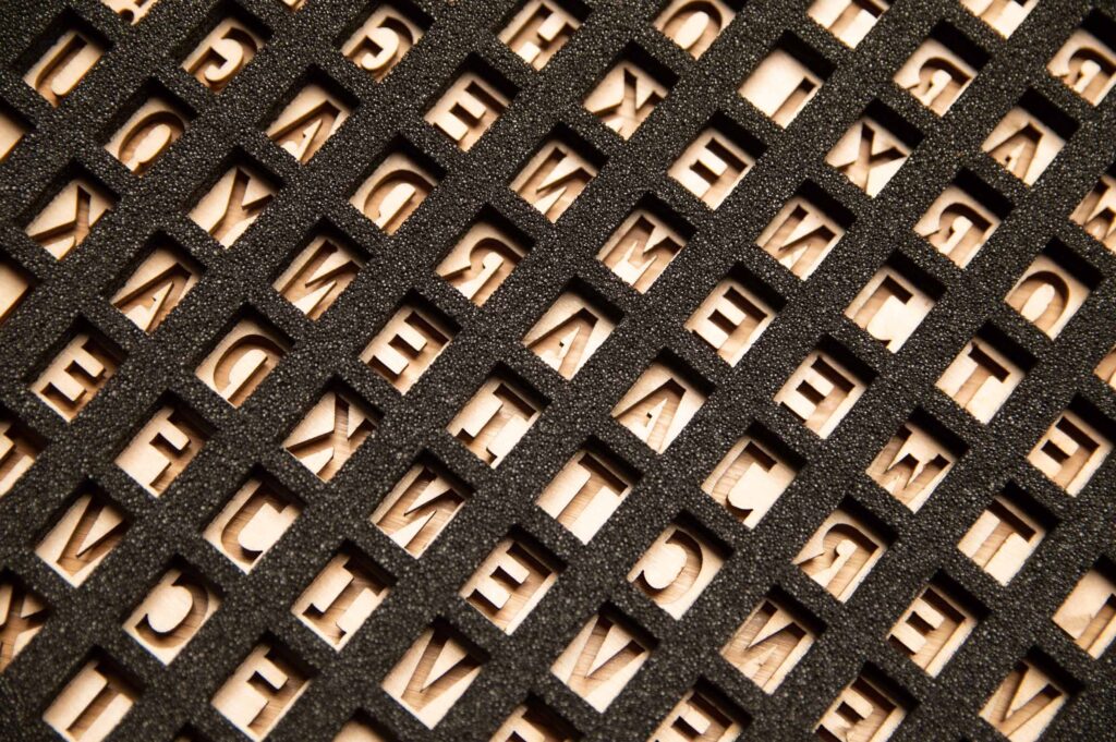
The first steps of the build process remain unchanged. I won’t go into the manufacturing of the clock face and the woodworking for the frame since I already discuss that in my other post. The basic ingredients are shown below: the only thing that’s new is the PE foam light grid. It has 121 cutouts that align with the letters on the face of the clock, and another cutout for easier access to the button electronics. Finally, some round cutouts for mechanical fasteners.

The enclosure is assembled, followed by a bit of soldering for the button wiring. The buttons have a common ground wire, three signal wires and a power wire for the integrated LEDs.

The lasercutting service that I use offers to apply an adhesive layer to one or two sides of a material before it goes into the machine. This is useful for the light grid, because it simplifies the assembly process: peel off the protective layer and stick the part into the enclosure.


For some reason, I really like this shot of the assembled light grid..!
Improvement: electronics
Like I said, I designed a PCB that integrates all the electronics. What also changed:
- I upgraded the LEDs to WS2813 (used to be WS2812B). WS2813 LEDs feature dual signal wires. Therefore, if one LED fails, the LEDs behind it in the chain will continue to work. I haven’t ever had a WS2812B LED fail, but it is a nice addition nevertheless and the cost per LED is more or less the same.
- Instead of using an RTC breakout, which typically also comes with a AT24C32 memory chip for some reason, I have now designed in the DS3231N chip itself.
- The Arduino Uno has been replaced by an Arduino Nano. I want to throw out the Nano in a future update, because I now have the knowledge to design a similar circuit and put it on the PCB directly. The reason I didn’t is because I didn’t know much about electronics design back when I designed and ordered these boards a few years ago.
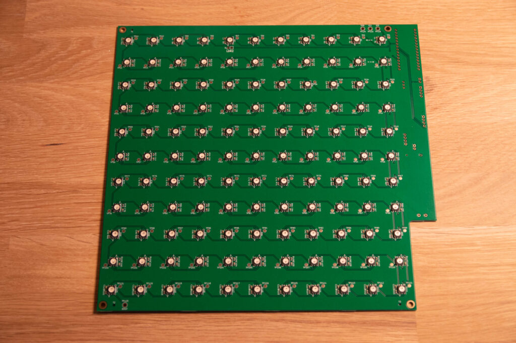
Some parts of the PCB remain unpopulated. I added these unpopulated circuits for other future upgrades such as Bluetooth connectivity, or dimming based on ambient light using an LDR.

Each WS2813 LED has its own resistor and capacitor. I think you could do without, but they increase the robustness of the LED chain. I also added a test point to every LED. It was useful once, because one of the five boards had a faulty LED and I isolated the problem using the test point corresponding to that LED.

The printed circuit board is assembled using four screws. It just sits on top of the light grid.

Done!