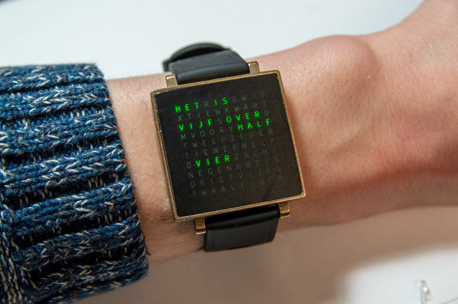
About a year ago, I had some time to spare over the summer and decided to challenge myself with a project that I call “Clocksquared Mini”. It is Clocksquared, but in a tiny wristwatch package. This gives rise to a major challenge, as everything has to be shrunk down approximately ten times from a 300x300x50 mm to an approximately 35x35x7 mm package. Moreover, running everything off of a coin battery whilst maintaining an acceptable battery life also is a bit of a challenge.
Electronics and software design
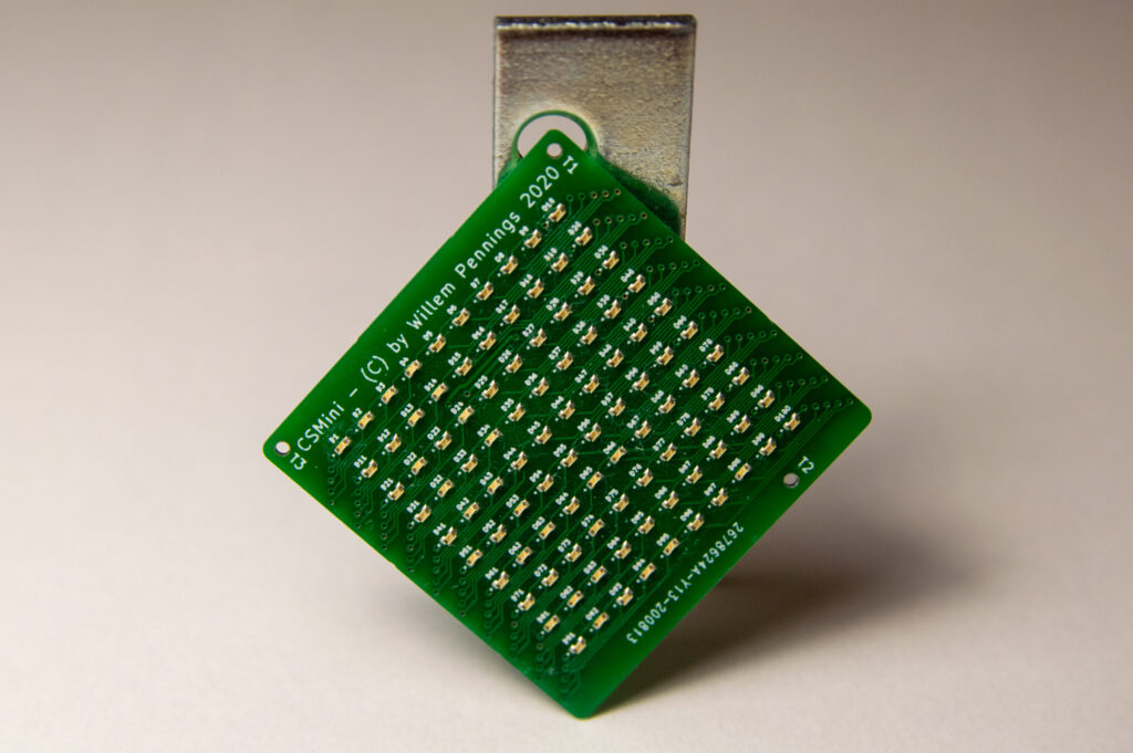
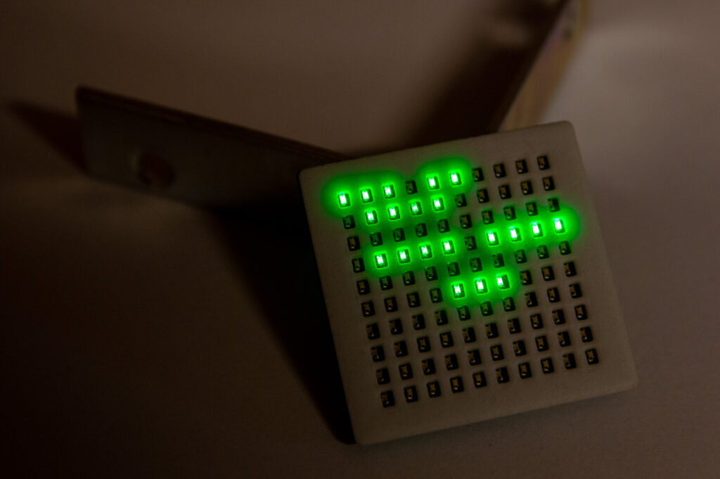
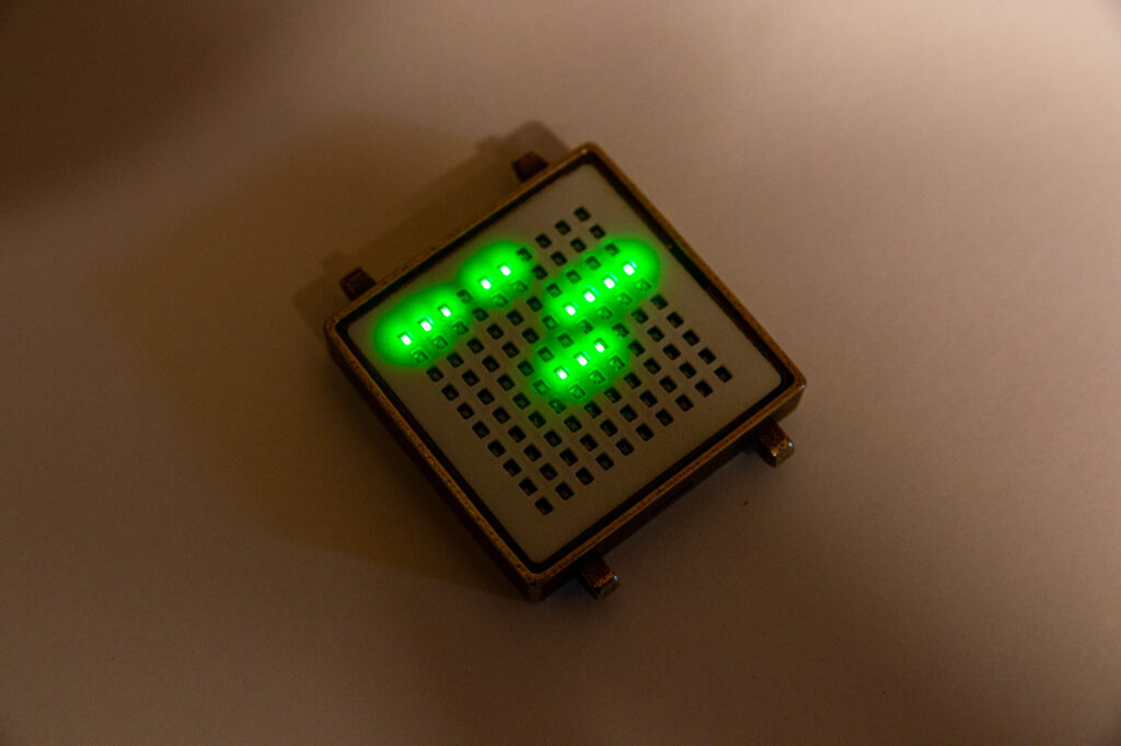
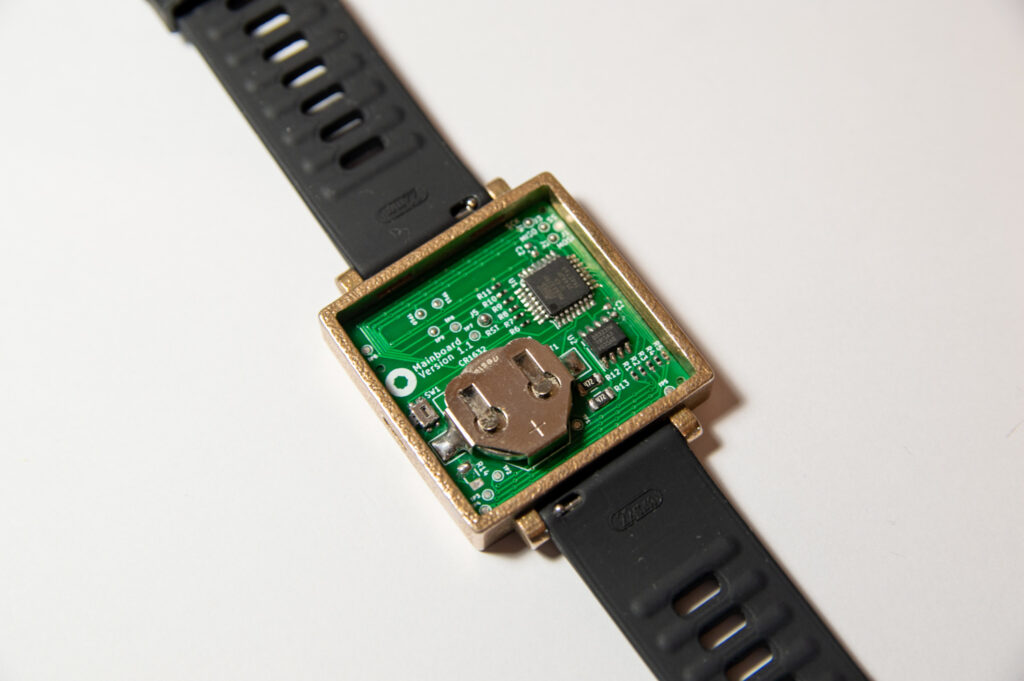
I first designed the PCB, which is a two-layer board. It features a 10×10 charlieplexed grid of 0402 LEDs (individually addressable). The back side of this PCB contains an ATMega328P microcontroller, a DS3231MZ+ RTC module and a CR16xx battery holder, amongst some other components such as some resistors and a push button. Note that I specifically chose the MZ+ version of the DS3231 RTC because it comes in a smaller package (SOIC-8) than the “normal” one. I had the PCB manufactured and assembled (top side only) by the manufacturer and soldered on the bottom side components myself. The firmware is a mix of my original ClockSquared firmware and a charlieplexing Arduino library that I found. It works quite well.
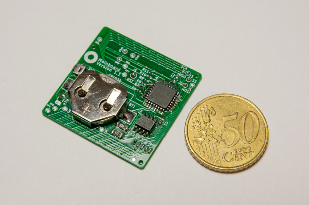
The battery is a CR1632 lithium battery and has a nominal capacity of about 130 mAh. It’s not much, but then again, the watch does not have to use a lot of power. I spent quite some time optimizing the firmware for ultra-low power usage. Whenever the watch is not in use, the processor turns off practically every internal circuit it can except for that one circuit that wakes it up when the wake button is pressed. When powered on, it runs at 4 MHz instead of the typical 16 MHz to save some more power. When the button is pressed, time is shown for 5 seconds after which the ATMega328P goes into deep sleep again. This PCB has been powered for over a year now using the same battery with me occasionally powering it on to check that it still works. The voltage still hasn’t dropped below 3 V. Good!
Designing the lighting part
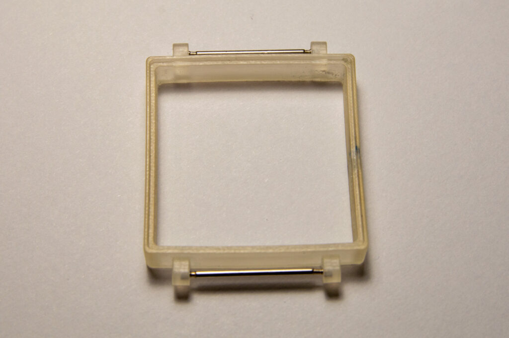
Like with the “regular” version of ClockSquared, the LED matrix needs a so-called “light box” to keep the light from the one LED from bleeding to the others. This part was pretty straightforward to design and manufacture. It’s made by Shapeways using their regular SLS 3D-printing process and came out fine. The rectangular holes are 2.0 mm high and 1.5 mm wide.

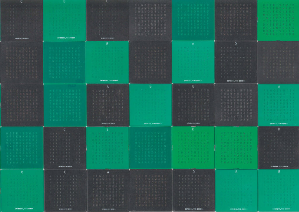
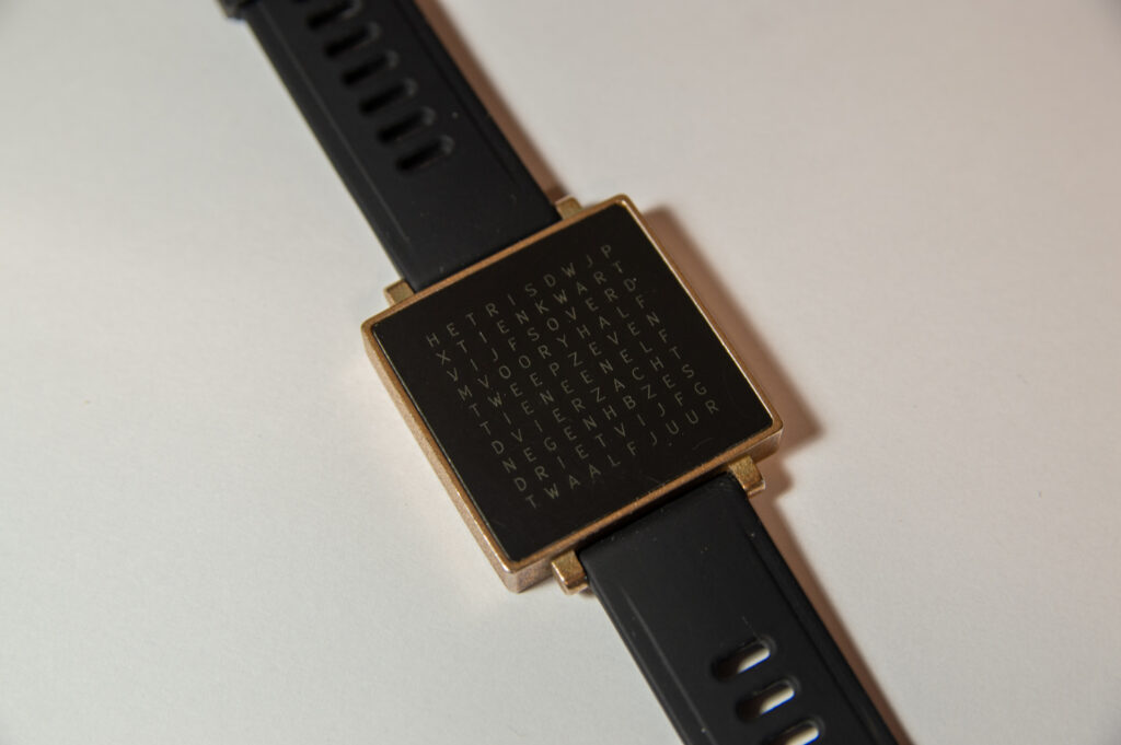
The most challenging part in this design is the front plate, by far. How does one manufacture a front plate with letters that are barely 2 mm tall, and still feature good resolution and readability? For my solution, I was inspired by a YouTube user called sjm4306. I came across his excellent idea to use a thin PCB with only a solder mask pattern with the 10×10 letter grid that defines the clock face. The 0.8 mm thick FR-4 PCB material acts as a diffuser and the solder mask pattern ensures that only the letters can light up. The result is quite good, with much better resolution than I had expected. Previously, I was worried that I would’ve had to use e.g. micromilling techniques to obtain this front plate; who knew conventional PCB manufacturing techniques would yield a much better, simpler, cheaper and more scalable result?

There is just one problem which I still have not fully solved and that is that light is dispersed within the FR-4, causing some significant bleeding to letters surrounding the ones that are lit to display a word. It occurs inside the fiberglass material. You can’t really see this effect in the photos. I have tried heaps and heaps of different front plate designs, each slightly different than the other. Here are some things I tried to get this right:
- Either increasing or decreasing the width of the PCB. I tried 0.6 mm, 0.8 mm and 1.0 mm and didn’t really notice much of a difference between these options. In my opinion, the PCBs with a thickness of 0.8 mm turned out best so I kept using that thickness.
- Varying the width of the letter strokes on the back side of the PCB between 100 um and 300 um. 100 um strokes are too thin for the process to properly reproduce. Wider strokes let more light through and thus increase bleeding, but if not enough light comes through, the words become too hard to read in daylight conditions.
- Using only a single thick vertical stroke on the back side of the PCB to limit dispersion in horizontal direction as much as possible. This doesn’t work as it very much disturbs the illumination of letters on the front side of the PCB.
- Instead of just applying a soldermask layer with the letter pattern, I tried adding the copper layers with an identical pattern as well. The overall result is a bit better, mostly in terms of surface finish, but light still bleeds through adjacent letter openings and doesn’t really penetrate the solder mask anyway.
- Using 4-layer PCBs instead of 2-layer PCBs didn’t really help much though conceptually it’s pretty clever. The idea is that if light must pass through more layers (with the same pattern), only rays that go (nearly) straight pass through uninterrupted. The problem however is that the stackup of 4-layer PCBs is such that the inner layers are still very close to the outer ones, leaving plenty of room in the middle (approx. 0.5-0.6 mm in a 0.8 mm PCB) for light to disperse sideways.
Below is a picture of just a few of my prototype front plates. I ended up going for a 2-layer PCB with 200 um wide strokes and an additional copper layer on the bottom side of the PCB only. Results are “OK”, but not perfect. I think this problem cannot be resolved without using a different front plate concept altogether. It is very hard or even impossible to get rid of the internal light dispersion. Conceptually different solutions that I thought of are:
- Using an etching process (like with PCBs), but using a nontranslucent material (a plastic or metal) and etching through it.
- Micromachining the letters. I expect this to be (very) expensive and I’m not sure if it can be practically done at this resolution.
- Lasercutting. I like this concept the most because it is simple. The only challenge so far is to find a single-stroke stencil font.
Enclosure design and band selection
With all this lighting business out of the way, I focused my efforts on designing an enclosure. Its requirements are pretty straightforward. The enclosure must be stiff and robust and made of a material that is skin-friendly. Dimensional accuracy needs to be fairly high but 3D printing has come a long way in recent years so I chose that route again.

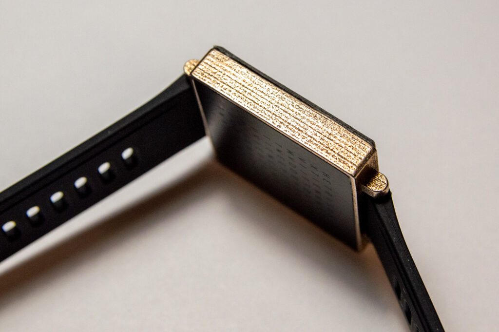
I started with a relatively simple design that didn’t yet feature a back cover and had that manufactured from a clear plastic. At this point, I just wanted to get the size, look and feel right. Though this initial design was structurally sound, I made some minor changes for a second revision, including a larger hole for the push button and a larger distance between the protrusions to which the bands are attached. For the second iteration, I chose to have it manufactured out of brass for a stronger and more durable result that also has a “premium” feel to it. The dimensional accuracy is worse using this manufacturing process but I was happy to make some manual adjustments to the part to make everything fit together.


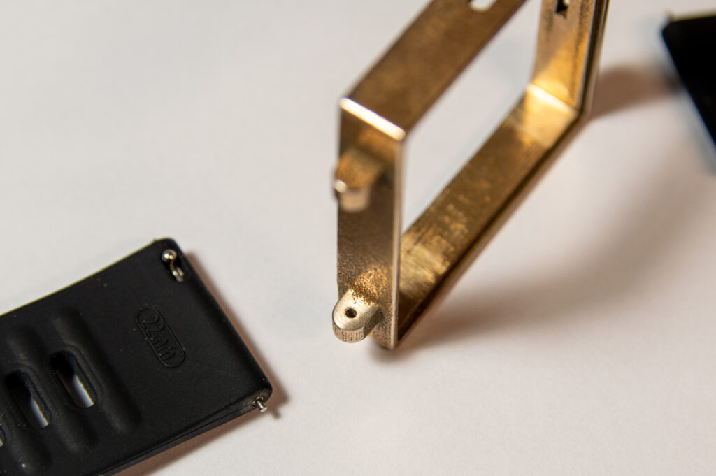
The brass frame came in and I was quite happy with it. I did have to file down the internal corners a bit for the components to fit. I was surprised that the band attachment holes came out so well, given their very small diameter and relatively high hole depth/diameter ratio.
I purchased some watch bands online after searching around for a bit. The first ones I ordered turned out to be just right. These have an integrated lever to pull in the telescopic rod slightly. This is quite nice because it eliminates the need for any additional equipment or parts. I think these bands were originally designed for some other existing (smart) watch.
Putting it together
The assembly process is straightforward but slightly tricky because no screws are involved. I chose to use glue to put it all together. In particular, super glue to fix the front plate and light box in place and regular hot glue to secure the PCB to the frame.

The push button on the PCB does not protrude far enough to stick out of the frame, so I had a tiny button 3D-printed which I intended to place in a hole in the frame directly in front of the button. Unfortunately it didn’t fit well, so I still have to come up with a new design for this button. For now, I’m just using a pointy object to wake the watch.
A newer revision of the PCB is slightly notched around the area where the button sits, such that there is more free space around the button.
The back cover is a 3D printed Nylon part that is manufactured using the MJF printing process. I had originally envisioned this part to clip into the frame using a clip design that is often found in injection moulded parts. This didn’t work so well, maybe due to the compact size of the watch. Anyway, I filed off the clip that I had designed and simply glued the cover in place using hot glue. It sounds a bit cheap and stupid and honestly, it is. Nevertheless, it looks good from the outside and I don’t plan on opening up the watch very often.

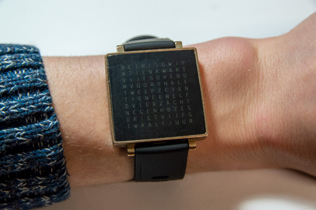

Done! As you may have noticed, this project was quite challenging with respect to manufacturing techniques and material selection and certainly is still classified as a prototype. I’m happy with the result but I’m quite sure that I’ll keep trying some new techniques to come up with an improved version of this watch. Have you got a clever idea? Please share it with me using the comment section below!
I want this.
This is really cool. Will files for this be posted on GitHub?
Hi Vish, unfortunately I lost some of the files for this project, so unless I manage to recover them, the answer is no.
The commercial version: QlockTwo W
https://monochrome-watches.com/qlocktwo-w-worlds-first-wristwatch-that-tells-time-in-words/