
For some reason, I’m intrigued by LEDs. Indeed, they can be found in pretty much all of my projects. I was recently inspired by one of Greg Davill’s projects, a miniature LED cube boasting a total of 3456 LEDs. After pondering about it for a while, I decided I’d attempt building one myself. This post describes the realization of this beautiful cube.
Hardware: PCBs
I initially guessed that assembly of the LED panels would be the most challenging part of this project, and it turned out to be true. I had succesfully attempted reflow soldering before, but that project didn’t require cramming 576 RGB LEDs onto a tiny square surface. The excellent people over at PCBWay.com were friendly enough to sponsor the PCB panels for this project. The boards are 1.6 mm thick and feature a black soldermask, ENIG finish and white silkscreen. I love this combination of colours. The boards are of excellent quality and so was the stencil that came along with it. If you’re looking for a reputable PCB manufacturer I’d happily recommend PCBWay. Nowadays, they also offer all other kinds of manufacturing services such as 3D printing and CNC machining but I’ve yet to try those services.


If you’re looking for details on the design of the electronics I would recommend reading Greg’s build post. In short, these panels are driven using a technique called multiplexing. Matrix rows are controlled by SN74HC595 shift registers that in turn control 24 MOSFETs. Six TLC59025 constant-current LED sink drivers control the rows. I started by assembling the bottom side of the panels. This is pretty straightforward since the components are all fairly large. Some panels required some rework after coming out of the oven, mainly due to solder bridges between leads on the TLC59025 QSOP-24 packages.


Next up: front side assembly. This was, quite obviously, more difficult. I knew that manually placing 576 2×2 mm2 LEDs would be cumbersome without proper equipment, so I purchased a Quick 381A vacuum pick/place tool. I’m really glad that I did, because it flawlessly does the job. Once I got the hang of it, I was able to fully populate one panel in about an hour.


I made some very instructive mistakes during the assembly of seven of these panels. Lessons learned include:
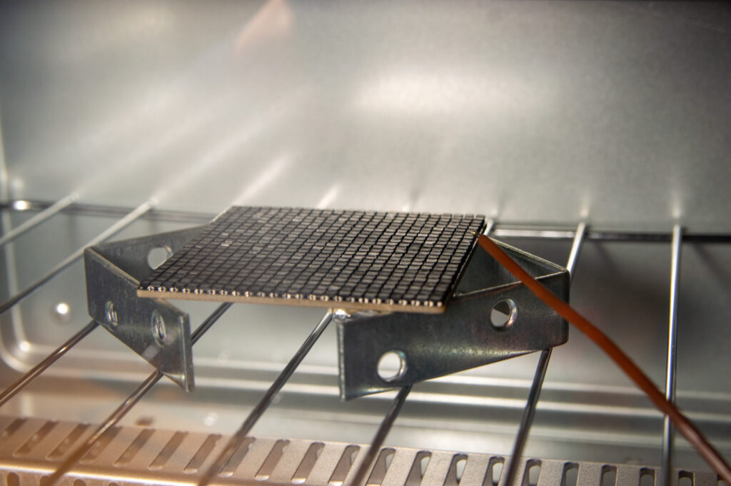
- Closely monitor and control reflow temperature, because if you don’t, LEDs will magically fail. On my first panel, a large band of LEDs in the middle of the PCB failed, but only the red ones. I couldn’t figure out why until I realized these LEDs had been directly above the ceramic heating element in the oven… Aha!
- It appeared that alignment of the stencil on the PCB had to be fairly accurate and smearing had to prevented at all costs. I reflowed a PCB that had a tiny amount of smearing in one corner and it resulted in a bunch of bridged leads. I ended up having to rework about 10 LEDs on a single PCB because of this.
- Fix the temperature probe in place so that it cannot knock a bunch of LEDs off the PCB when you open the door at the end of the cycle…

Hardware: frame
I designed the frame for the cube myself and decided to keep it as simple as possible. Its size is 67 mm3. It’s a single part, can be 3D-printed and secures the PCBs in place using drafted edges. I chose to have this printed using Shapeways’ MJF printing process. It came out nicely, though the dimensional accuracy was not as good as I had hoped it to be. Initially, the fit of the panels in the frame was too loose, but this was solved by simply applying tiny amounts of superglue to the PCB edges and letting that dry out overnight.


Programming
I couldn’t find any programs or libraries that were directly compatible with the hardware on these panels so I wrote my own. Using Greg’s controller and gateware/firmware currently is not an option because the ongoing chip shortage has made sourcing the necessary parts all but impossible. Anyway, I only have a limited number of microcontrollers lying around and pulled out an Arduino Uno to begin with. I programmed most of the multiplexing code using low-level port manipulation instructions, which makes the program a whole lot faster compared to one that is heavy on functions like digitalWrite. Conceptually, the program is quite straightforward: configure a timer to trigger an interrupt every 1/2400 seconds. Each time, read and shift out a bunch of data, latch the registers and wait for the interrupt signal to do it all over again.
It’s a pain to debug code like this , but once it works, it works and it’s pretty quick too. The Uno is not capable of generating many fancy animation patterns at all, but I was able to get a really nice random sparkle animation going using only 3-bit color! I was a bit surprised about this.
Testing, assembly, results
Each of these steps was pretty uneventful. The panels are daisy-chained and hooked up to the Uno. Everything works!
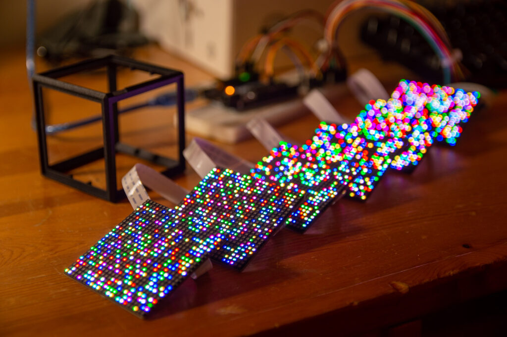


Final assembly is a bit of a puzzle, mainly because you can (try to be) smart about the orientation of the panels inside the cube to ease routing of the flexible flat cables. I couldn’t be bothered too much, partially because I’m not yet trying to fit batteries and a controller inside the cube. This is something I’ll get to later.


Done! I love the end result. I was so excited about the end result that I didn’t want to delay publishing this post until I sourced batteries and a controller. Again, huge thanks to Greg Davill and PCBWay for enabling me to execute this project. It has taught me a lot about the software side of controlling LED arrays. Moreover, I’ve greatly refined my PCB assembly and rework skills.


OMG, fantastic idea and build. Thanks for sharing.
Absolutely stunning!!!
That’s gorgeous! I’d love to see a video of the sparkle =*).
Thanks! I’ve just added a small video of the animation near the bottom of the post. Hope you like it!
Hey, looks amazing!
What did you pay for the parts, approximately?
Thanks! The parts are worth approximately €200 total. €100 for enough electronic components to make 7 panels (1 spare), €30 for the 3D-printed frame and €50 (depends on where you order them) for the PCBs and another €20 or so for consumables such as solder paste etc. This is not the full cost since a control board and battery are also required but I have not yet sourced or developed these.
Would be cool to see a session of the Game of Life running on that
Was thinking the exact same thing.
Omg..thank u
Wow. I would love to see some more demo code on this. Like in this Christmas Tree 3D demo: https://www.youtube.com/watch?v=TvlpIojusBE
I would buy this. Kickstarter?
Absolutely love this project–it’s a fantastic build! Are you familiar with FastLED by Jason Coon? It’s a open source library for running colored LEDs on Arduino: https://github.com/jasoncoon/FastLED
#kudos
Much appreciated! I’ve used the FastLED library before in some projects, for example the most recent word clocks I’ve built. They’re using WS2812 or APA102 individually adressable RGB LEDs. It’s a useful library!
wow this is mind bending!
care to share the build instructions?
This is an amazing build and a great description of the process you went through, including mistakes and how you rectified them. Well done.
So materials cost at least 400 EUR? OK, I’d easily buy a pre-assembled one for 600 EUR. Sigh. I want one!
EE here. Superb piece of work ! So Cool !
Just watched your M&M color sorter and balancing cube videos, too! You are very talented and an inspiration. All fantastic builds! Watching your LED cube video, a programming idea came to mind. Optionally, you could implement the classic Conway Game of LIFE program with variations on that theme, based on dot colors. Might be interesting to watch those critters crawling around your cube. Just a thought. https://en.wikipedia.org/wiki/Conway's_Game_of_Life